|
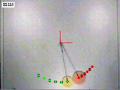
Figure 1. Two pucks have a rotational collision on an air table. |
Figure 1 shows a picture of two pucks on an air table. The two pucks interact (collide) while following a circular path. During the interaction (collision), the large puck applies a force on the small puck and the small puck applies a force on the large puck. These are action-reaction pairs.
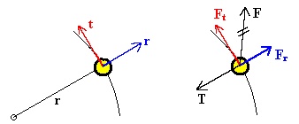
Since the objects are not following linear paths, it is useful to choose a different coordinate system. Figure 2 shows a mass following a circular path. On the left, a coordinate system is shown with t indicating a direction tangent to the path and r indicating a direction perpendicular to the path along the radial line. A free body diagram is shown on the right, where a force other than the tension is applied to the mass. This force is broken into components along the path Ft and perpendicular to the path Fr.
Analyzing the free body diagram in the radial direction we have:
Fnetr = mar or T - Fr = mvt2/r
This is the same result as uniform circular motion. Here, vt is used to note that v has a direction tangent to the path. Now, since there is a tangential force Ft, there will be a tangential acceleration at and vt will not remain constant. Analyzing the free body diagram in the tangential direction we have:
Fnett = mat or Ft = mat
Here, the tangential force causes the mass to accelerate in the tangential direction. With this motion, it is easier to work with rotational equations. Table 1 shows the relationships between linear and rotational motions. While you have seen q and w in the section on Uniform Circular Motion, a, I, L, and t are new to this experiment. They are discussed below.
Table 1. A list of relationships between linear and rotational motions. Angles must be measured in radians. The subscript t means tangent to the path or perpendicular (^) to the radial lines.
| Linear | Rotational | Relationship |
| Ds | Dq | Ds = rDq |
| vt = Ds/Dt | w = Dq/Dt | vt = rw |
| at = Dvt/Dt | a = Dw/Dt | at = ra |
| m | I | I = Smiri2 |
| pt = mvt | L = Iw | L = rpt |
| Ft = mat | t = Ia | t = rFt |
Angular Acceleration
Angular acceleration is defined as the change in angular velocity with respect to time.
a = Dw/Dt
Notice that the angular acceleration is the slope of an angular velocity versus time graph. The SI units for angular acceleration are 1/s2.
Rotational Inertia
Rotational inertia, I, depends on the object's mass and how the mass is distributed from the axis of rotation. In general, if the object is broken into small masses mi, each at a radius ri from the axis of rotation, then we define I as:
I = Smiri2
Here, m is the mass in kg and r is the radius of the circular path in meters. The SI units of rotational inertia are kg.m2.
Angular Momentum
Angular momentum, L, is the product of the object's rotational inertia and its angular velocity.
L = Iw
Here, I is the rotational inertia and w is the angular velocity. The SI units of angular momentum are kg.m2/s.
In Table 1, the relationship between L and p is written:
L = rpt
This means that the magnitude of L equals the magnitude of r multiplied by the magnitude of the momentum tangent to the path. We can also say that the magnitude of L equals the magnitude of r multiplied by that part of the momentum that is perpendicular to the radial line. This is written:
L = r^p
Torque
The net torque, t, acting on an object is the slope of its angular momentum versus time graph.
tnet = DL/Dt
The SI units of torque are kg.m2/s2 or N.m.
If the object's rotational inertia doesn't change, then the net torque is also the product of the object's rotational inertia and its angular acceleration.
tnet = Ia
In Table 1, the relationship between t and F is written:
t = rFt
This means that the magnitude of t equals the magnitude of r multiplied by the magnitude of the force tangent to the path. We can also say that the magnitude of t equals the magnitude of r multiplied by that part of the force that is perpendicular to the radial line. This is written:
t = r^F
Newton's Third Law Revisited
Newton's third law says that if one object exerts a force on a second object, then the second object exerts an equal but oppositely directed force on the first object. This is shown for two pucks in the left drawing of Figure 3 where F12 = - F21.
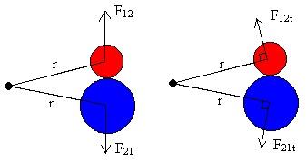
Examining Figure 3, and realizing that F12 = - F21 from Newton's third law, we see that:
rF12t = - rF21t or r^F12 = - r^F21
Here, ^ means we use the perpendicular components of the radial arm and the force. However, these are torques (see Table 1 in the Discussion section), so we can write:
t12 = -t21
Now torque is the slope of an angular momentum versus time graph so we can write:
DL1/Dt = -DL2/Dt
This says that when the objects are interacting, the slope of object 1's angular momentum versus time graph is the negative slope of object 2's angular momentum versus time graph. You can check the validity of this equation, and Newton's Third Law, by finding the slopes of the angular momentum versus time graphs.
If the above equation is valid, then:
DL1 = -DL2
This is true since the objects interact for the same amount of time. This says that the loss in angular momentum of one object equals the gain in angular momentum of the other object. Expanding we get:
L1f - L1i = -(L2f - L2i)
Here, the subscripts i and f mean initial and final respectively. Rearranging we have:
L1f + L2f = L1i + L2i
And finally:
LTf = LTi
Here, the subscript T means total.
If the above mathematical argument is physically valid, then we can make a statement about the total angular moment under certain conditions.
Conservation of Angular Momentum
If the only important torques acting on two colliding objects are internal torques, then the objects' total angular momentum is conserved.
Rotational Inertia
In this experiment, the mass is an air table puck. The puck travels in a circle with radius, r. Since the radius of the puck is small compared to the radius of the circular path, we can treat the puck as a point mass. Then the rotational inertia is:
I = mr2
You should check the values for the rotational inertias in the computer. The values can be changed with the Mass 1 and Mass 2 buttons if they are not correct.